Injector Change Procedure
By Mike Fleming
So let’s say you’re really bored one weekend (or evening) and it’s raining (or snowing!) outside and you decide you’d like to pull and swap injectors in the SVO since you have nothing else to do. Or maybe you just bought a new fuel management system, got that T3/T4 hybrid turbo installed and have calculated that you need more fuel, and ordered the proper injectors. Or you just got a new set of injectors that match your cars color.
In my case I’m changing over to a MAF measuring system and using an EEC tuner to manage the system on my relatively fresh engine. My recent fuel requirements calculations indicate that I need between 48 and 55 Lbs/Hour of fuel to make my power  goals. So I selected a set of 550cc/min injectors from Russ Collins Engineering (www.rceng.com). These units are a disc-type injector (non-pintle). They’re rated at 550cc/min, which translates to 52.3809 Lbs/Hr (cc/min divided by 10.5 = Lbs/Hr). We’ll need this value later so make a note of it. They came with a flow spec sheet showing how closely matched the set of four is.
Enough talking. Let’s get down to business and swap these injectors.
Familiarize yourself where things are in the engine compartment.
If there’s a possibility you might be interrupted before the system is completely back together, mark up a large piece of paper and tape it to the steering wheel indicating that the fuel system is open and to not try to start the car. But we’ll disconnect the battery anyway (defense in depth).
Bleed off the fuel pressure in the system. Use a MitiVac on the FPR hose and then let the engine sit for another hour. This should bring the pressure down to a serviceable level. There are tools available for removing the pressure also. Note that even there’s no pressure, the lines and fuel rail are still full of liquid fuel so have shop towels handy to collect any spills.
If the engine and injector area isn’t clean, then clean it first. Remove and stash the dipstick. Remove and stash the charge cooler, plug the hole for the compressor outlet

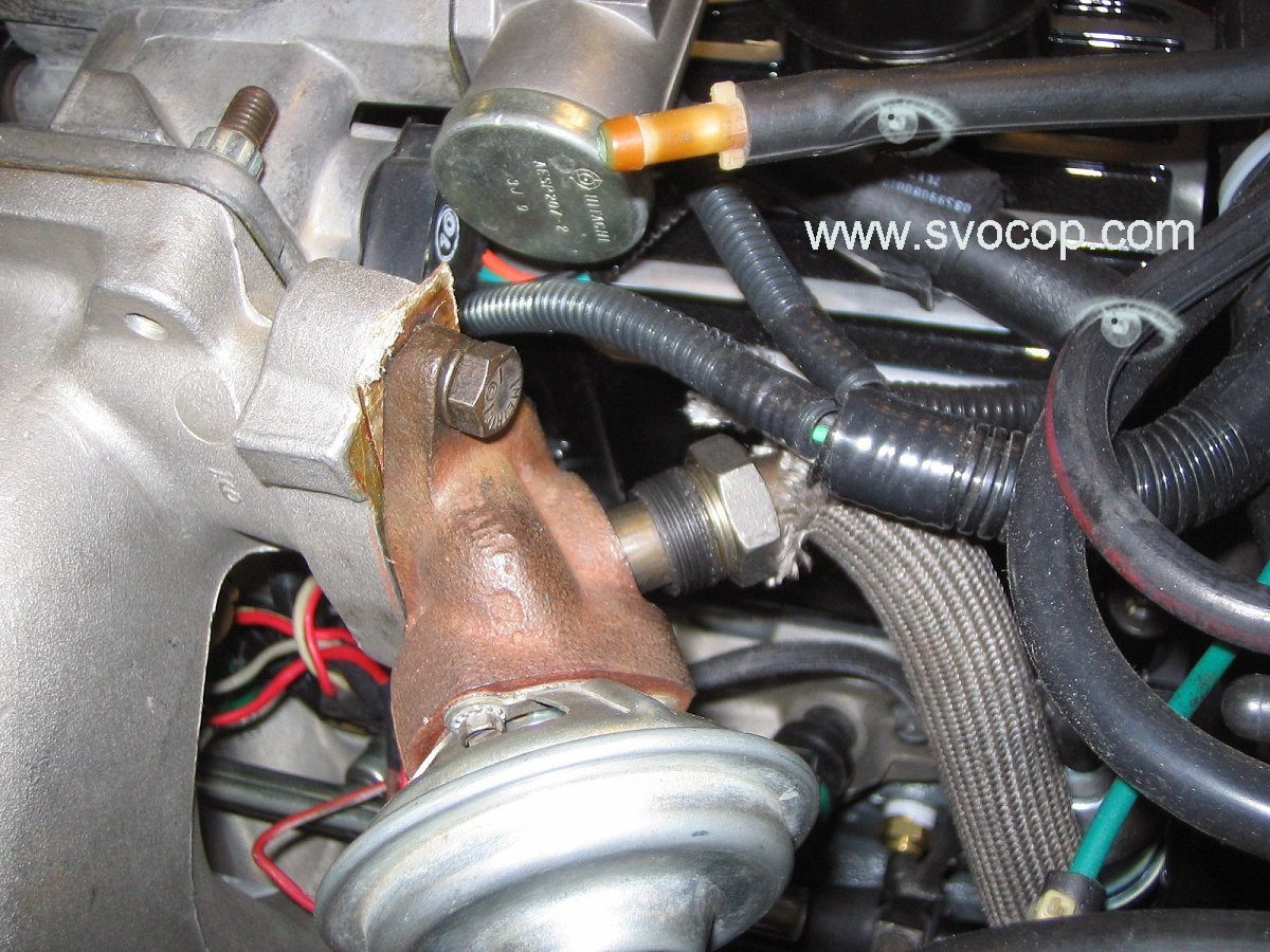
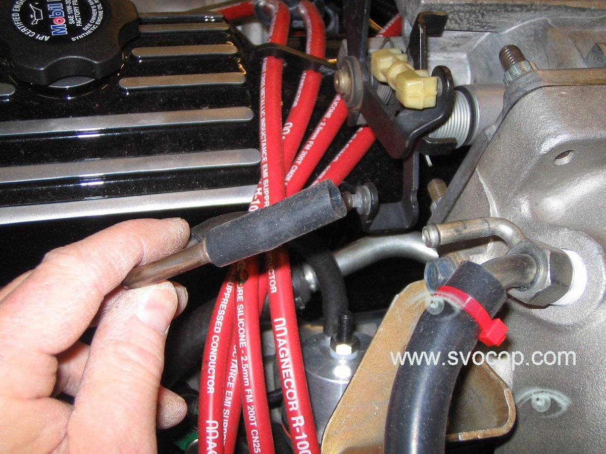
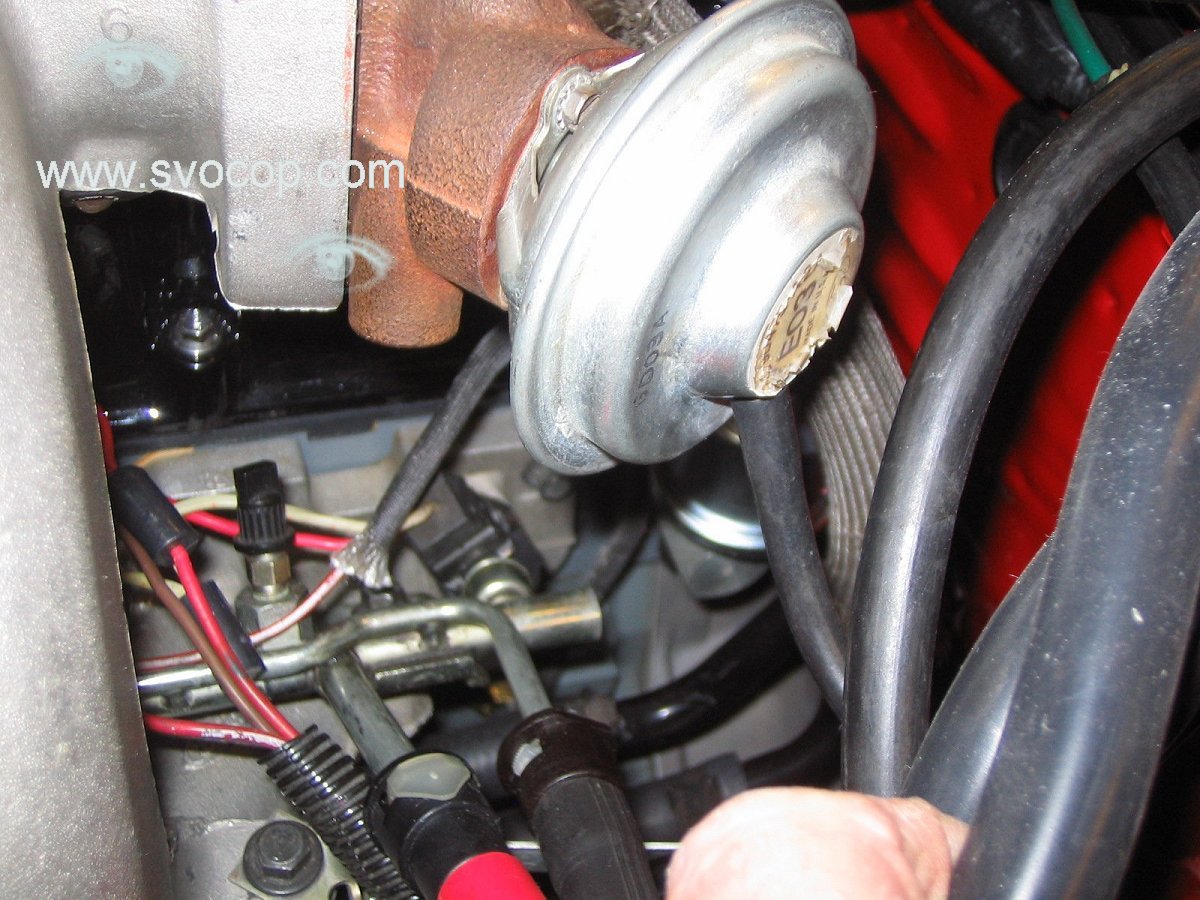
Loosen the EGR tube where it connects to the exhaust manifold adapter. It’s a 15/16 hex, loosen 1/2 to 1 full turn but no more. This end will stay in the adapter. 
Loosen and remove the nut from the intake side of the tube at the EGR valve. Same 15/16” hex.
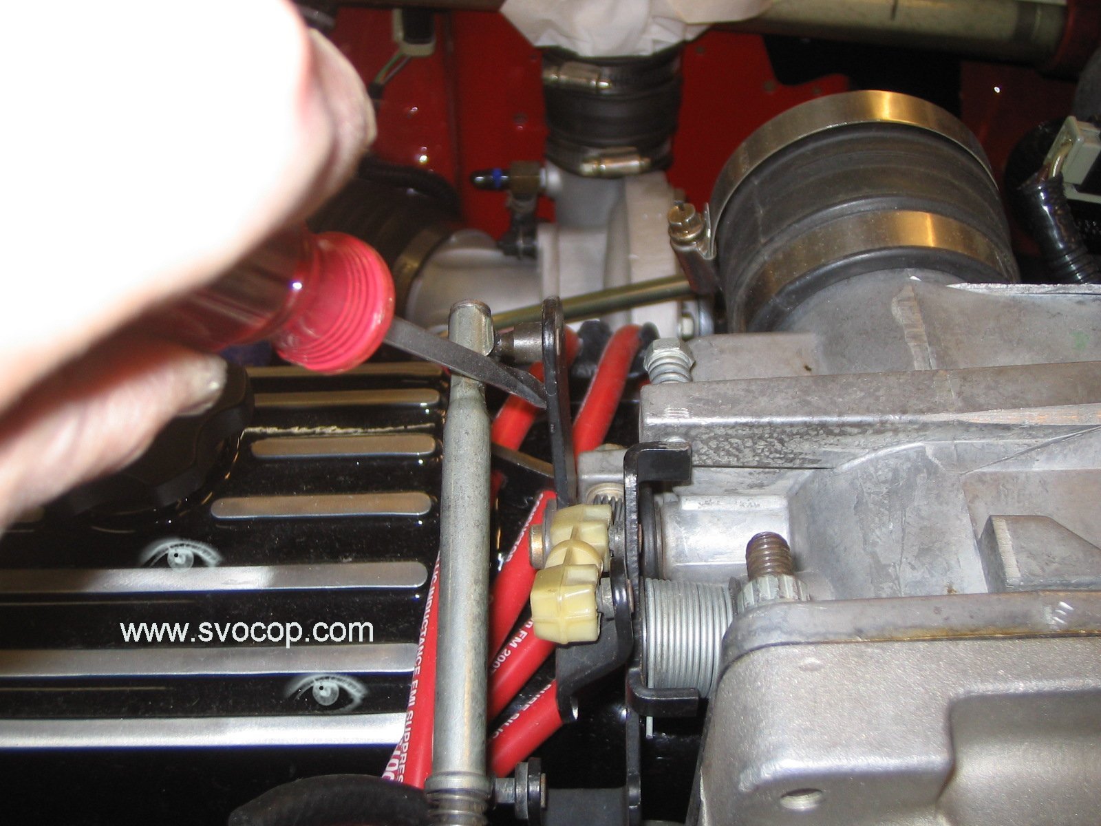 Pop off the throttle cable from the ball pivot.
Disconnect battery negative cable from battery. Stash the end somewhere so it can’t fall back onto the battery.
 Remove the 3/8 hex-head sheet metal screw that holds on the throttle cable and stash the cable out of the way. I put the screw back into the original hole so it doesn’t get lost.
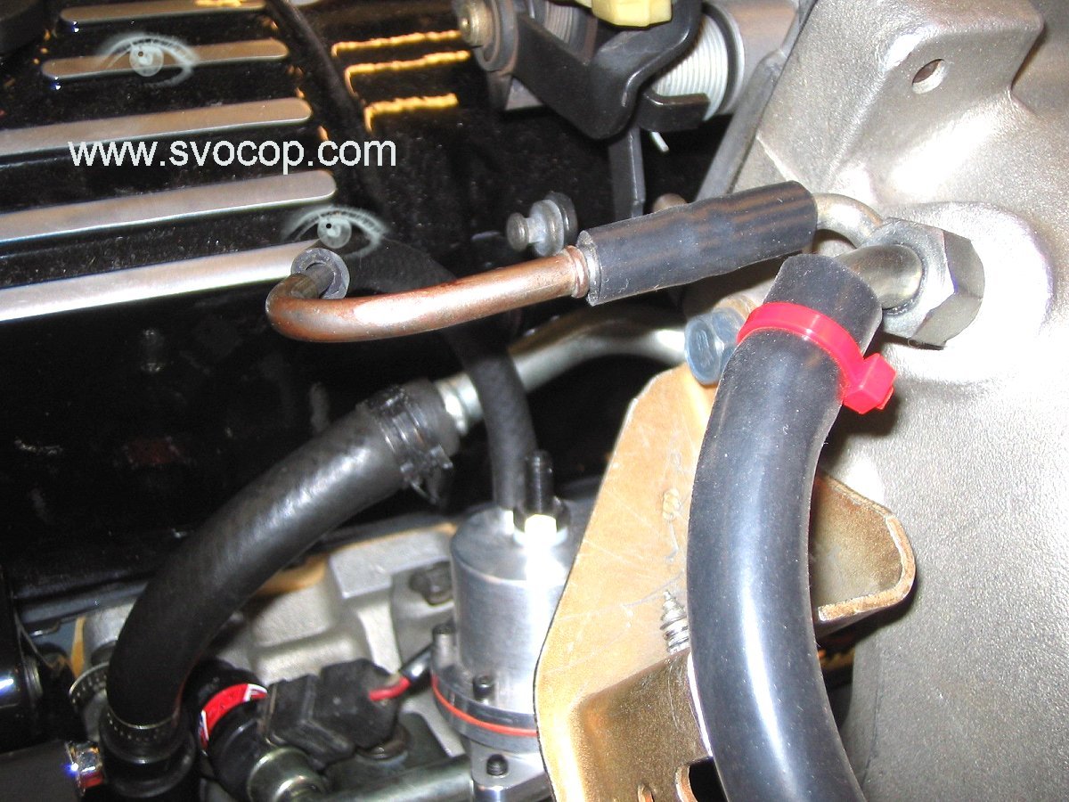
Pull off the fuel pressure regulator vacuum/pressure line at the manifold fitting.
 Pull the PCV valve out of the lower hose (leave it in the upper hose).
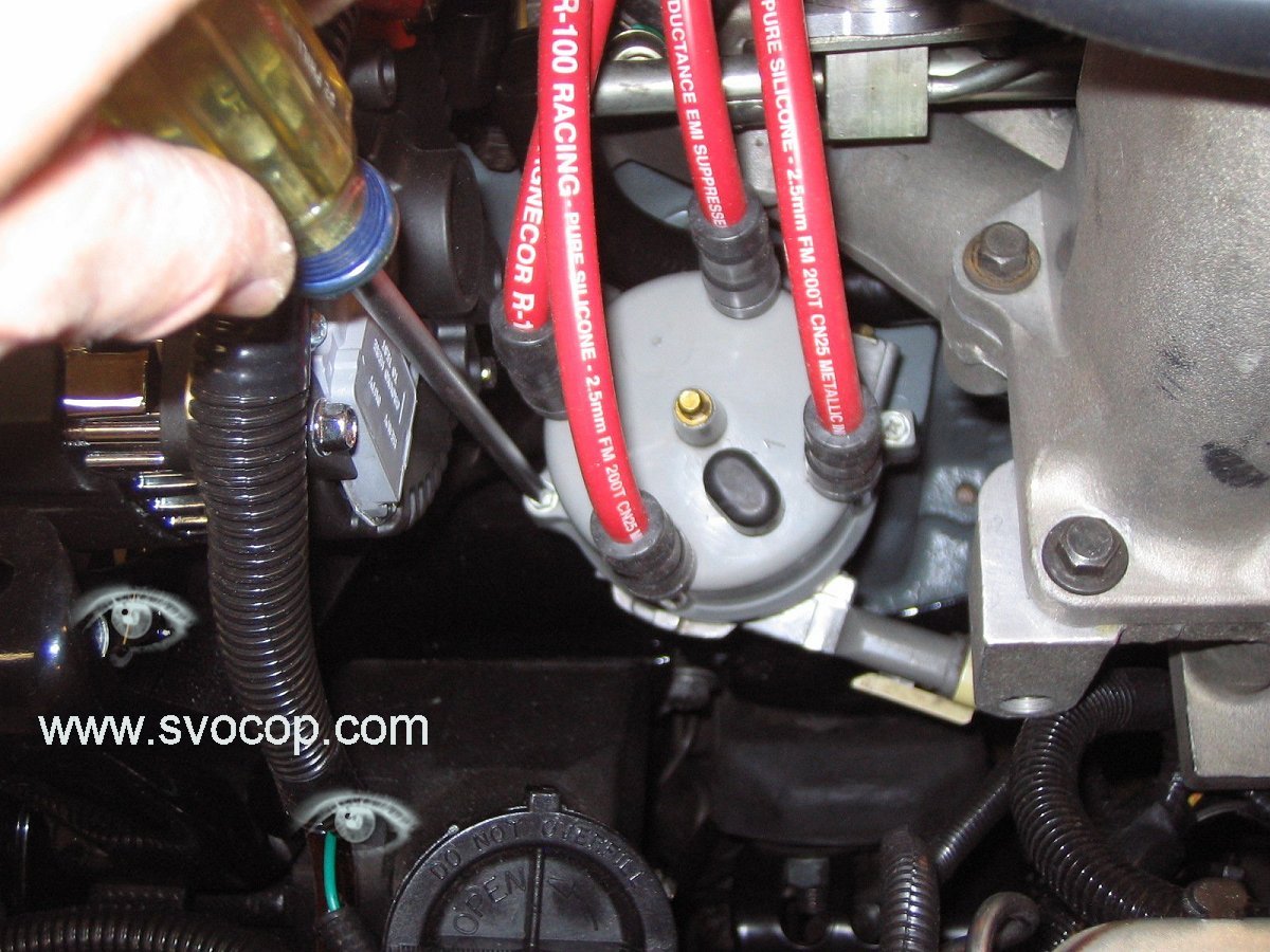
Remove the distributor cap (leave wires on cap) and swing the cap and wires out of the way (like onto the exhaust side of the engine).
 I have a custom bracket that holds the dip stick tube onto the rear, inner manifold upper-to-lower mounting bolt so I remove that first and swing the tube bracket out of the way (leaving the tube in place in the block).
The stock mounting bracket bolts the dip stick tube to a bracket that’s held to the manifold by the two rear bolts, if my memory serves. I’d just remove the two manifold bolts and leave the tube attached to the bracket. That stock tube bolt is really difficult to get to.

Disconnect the electrical connectors from the IAC & TPS if you plan on taking the upper manifold completely off the engine (say for cleaning). '
 Remove the large vacuum/pressure line that connects near the FPR fitting. Here I just swing the manifold out of the way enough to change injectors since I know it’s already spiffy clean. Disconnect the EGR vacuum hose.
 Remove the other three manifold upper-to-lower bolts. Or however many you still have remaining.
Put down some padding to protect the paint and swing the upper manifold out of the way. You’ll need to clear the PCV upper hose from the FPR hose & tube, and clear the EGR tube at the rear. If any of the wiring or vacuum/pressure lines are too short, remove or disconnect them first.
 Cover the hole openings in the lower manifold. I use the easily-removable blue masking tape.
If you drop something in there, it can ruin your day. If you don’t know you dropped something in there, it can ruin a months paycheck.
Disconnect the electrical plugs from the injectors. Just grab the body of the connector and lift straight away. Place the injector harness ends out of the way.
On the square manifold, there’s two bolts that hold the fuel rail to the manifold. They’re both on top pointing towards the edge of the cam cover.
Place some tape on the edges of the nicely-finished cam cover to keep from scratching it and remove the two bolts retaining the fuel rail. These are 6mm threads, so they’re probably a 10mm hex on your engine (they’re 10mm on mine!).
With only hand pressure, gently move the injector bodies away from the lower manifold, leaving the bodies in the fuel rail and extracting the pintle end from the manifold. If the injectors are stubborn, use a wide flat blade screwdriver to gently lever the body away from the lower manifold. Be careful to not let an injector top pop out of the fuel rail when doing this (so you make much less of a mess). It’s very difficult to tell if an injector is stubborn by just looking at it but they seem to hang out in groups. If you find one stubborn injector, then you probably have more.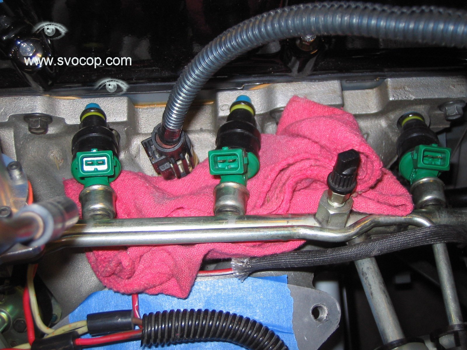
Place one of those shop towels under either the #2 or #3 injector, where the depression is in the lower manifold. This will collect the fuel still in the fuel rail without draining onto the engine or floor.
 Twist, rotate and pull the injector out of the fuel rail. Be careful if there’s still pressure there – maybe wrap a shop towel around the top of the injector and cover the fuel rail opening. Fuel will come out even if there is no pressure and the shop towel is there to collect it.
Make a note if the injector came out with the o-ring attached – if not, you’ll need to fish out the old o-ring from the fuel rail. A hook tool works well for this – being careful to not scratch the inside of the fuel rail hat cause that could cause sealing problems for the new o-ring (and replacement fuel rails aren’t normally available on weekends).
Move the shop towel over and remove injector #2 (magically there isn’t any pressure after removing the first injector). Then 1 & 4. Be sure to place the fuel-wet shop towel in a safe place to either evaporate or into a flammable storage container. Burning shop towels can ruin your day too. Remind me at a Reunion to tell you about the 930 fire.
Once the out-going injectors are out, verify that you didn’t leave any o-rings behind and inspect them (the out-going injectors) to see if they’re re-usable.
In this case, I clean and cap them and put them back into their original boxes. The out-going injectors are Bosch 803’s, which are rated at 42 Lbs/Hr and have a coil resistance of 4.4 Ohms.
If you’re planning on replacing the fuel pressure regulator, now is the time to do that. If you want to do that on the bench, you’ll need to remove the two fuel lines from the fuel rail. It isn’t necessary to remove the fuel lines and rail if you’re only swapping injectors.
 Open and inspect the new injectors. Make sure each has two o-rings that are soft, pliable and don’t have any splits in them.
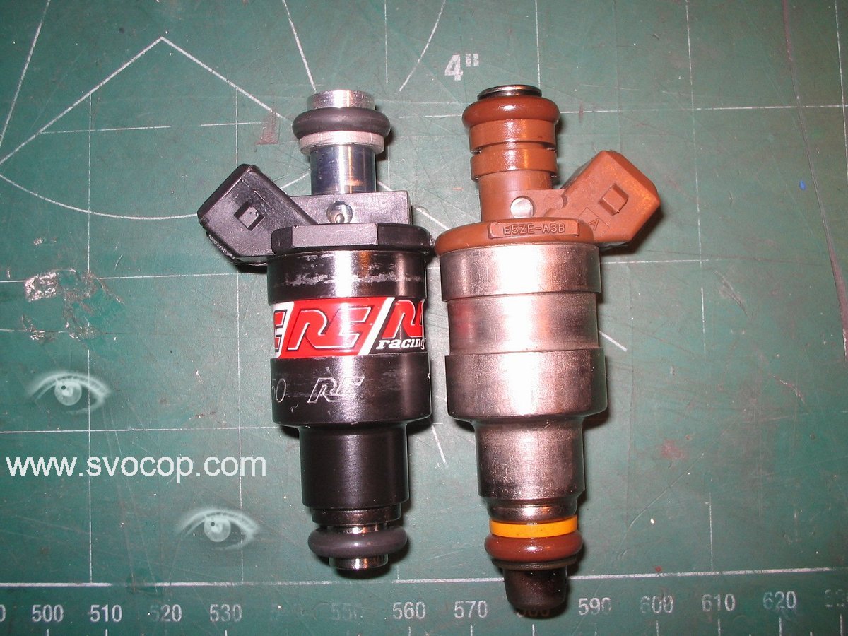
Verify the distance between the o-rings on the out-going and new injectors to make sure you’ve got the correct parts. This picture shows a stock 35 Lb/Hr Ford/Bosch injector, sometimes known as “Brown Tops” (which is different from “Copper Top” if you’re a Matrix fan).
Note the pintle end sticks out much farther than the disc style body, but the o-rings are the same size and in the same position.
 Additionally, when using new injectors that you’ve not tested before, check to make sure they installed the proper amount of Ohms in them. The stock ones typically measure between 2.3 and 2.4 Ohms. These RC units measure 2.20 Ohms.
Grab some Q-tips and first clean the bores that the injectors will install into (both the manifold and the fuel rail). Then oil the holes – I use Mobil 1 5/30 but any clean motor oil will work (do not use a silicone lube, WD40, etc.).
 This picture shows oil going onto the bore and the taper before the bore. This greatly assists in installing the new seals without tearing them. Do the same for the openings in the fuel rail. If a seal tears at the manifold, it will create a vacuum/pressure leak but won’t leak fuel. If an upper o-ring seal tears in the fuel rail, it will create a high-pressure fuel leak but won’t cause any manifold air leaks. Remember: the goal is no leaks anywhere.
Using the same or a fresh Q-tip, oil each of the eight new o-rings on the new injectors. Gently push each injector into the fuel rail opening.
Verify that the injectors are in straight, and that the o-ring didn’t get torn or pinched. We’ll check for leaks later. The stock Bosch bodies have a lot of plastic in the area to keep the injector body aligned. Make sure the injector is free to rotate inside the o-ring in the fuel rail.
Once all the injectors are installed into the fuel rail, align the set to the openings in the lower manifold and gently push each one in to the lower manifold.
You can push both on the fuel rail and each injector body, keeping alignment with all 4 injectors at the same time. Verify that each injector body can freely rotate (well, within the rather tight friction of the o-rings). If something seems amiss, stop and fix it.
 When the fuel rail mounting holes are lined up, then the injectors are positioned properly.
Start the bolts and tighten them to 10-12 Ft-Lbs with a torque wrench (OK, so maybe I’m a little detail oriented – BTW – anal-retentive is hyphenated!). I’ve never used locking compound on these bolts and have never had them loosen. YMMV.
 Re-fit the harness connectors.
Rotate the injector bodies to make more clearance if needed.
Connect the battery and switch on the fuel pump(s) for a second or two.
Not long enough to build full pressure. Check for leaks. If you find any leaks, fix them. If no leaks are found, turn the pump(s) on again and let the system build pressure. Leaks are very good at hiding so you need to be very vigilant at hunting them down.
 Put a finger or Q-tip under each injector where it plugs into the fuel rail – this is the first place to check for leaks (at the fuel rail and o-ring junction). Fix as needed. Trust me – it’s much better to find leaks now than after it’s all back together and being backed out for a test drive.
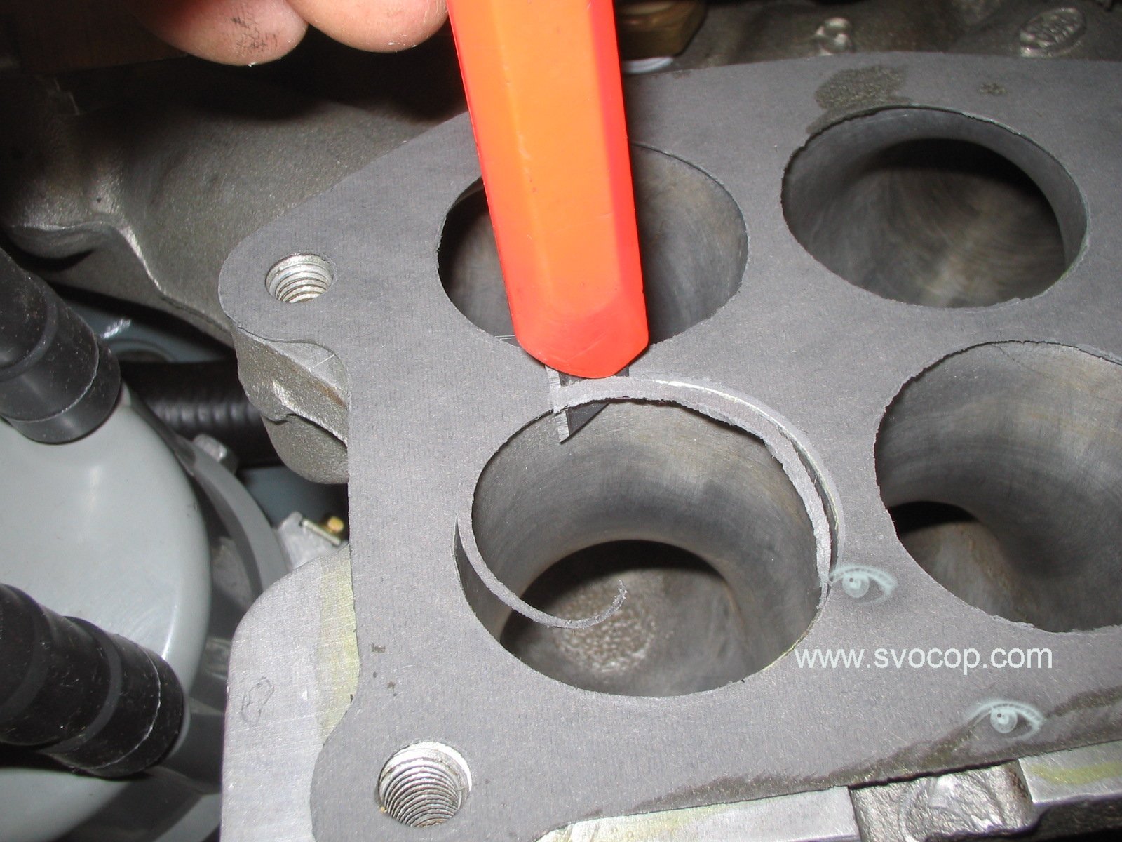
If appropriate, install a new upper-to-lower intake manifold gasket. Note that a new gasket will need to be trimmed to make the gasket holes large enough for the stock lower manifold ports, more so if you have a ported manifold. I use Gascacinch to mount the gasket to the lower manifold and cut the port holes out to match.
 Be sure to catch the gasket pieces as they try to drop into the ports. A shop vac can be your friend.
Now it's time to put things back on. Upper manifold – align the EGR tube and PCV hose. Start the EGR tube nut a few turns. Torque the upper-to-lower manifold bolts. 13-16 Ft-Lbs.
FPR vacuum/pressure hose fitting, throttle cable, any electrical or other vacuum/pressure hoses that were removed. Don’t forget the vacuum line to the EGR valve itself.
Re-fit the dist cap and coil wire. Re-fit the dipstick (and it’s always a good idea to top off the engine oil). Re-fit the charge cooler. Reconnect battery. Reset clock and radio, if needed.
Now it’s time to re-calibrate the fuel management system to work with the larger injectors. Here I change the injector size setting in PCMX software for programming my EEC Tuner card

Here’s where we need the new flow rate listed above. Send the new data to the EEC Tuner card, install in car and now it’s time for testing. My favorite part.
Until we met again…
More pictures: